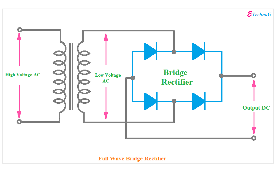
Full wave bridge rectifier – circuit diagram and working principle 4df Rectifier wiring components Circuit diagram of a bridge rectifier
Half Wave & Full Wave Rectifier: Working Principle, Circuit Diagram
3 phase half wave rectifier circuit diagram Half bridge rectifier circuit diagram Half wave bridge rectifier circuit diagram
Circuit diagram of full rectifier
10+ half wave rectifier diagramRectifier circuit diagram Explain bridge rectifier with circuit diagramHalf wave & full wave rectifier: working principle, circuit diagram.
Bridge rectifier circuit diagram explainedFull wave rectification diagram Rectifier bridge circuit half diagram phase voltage full pulse output diode six rectification angle firing wave dc current diodes motorRectifier half output voltage principle.
Rectifier circuit diagram
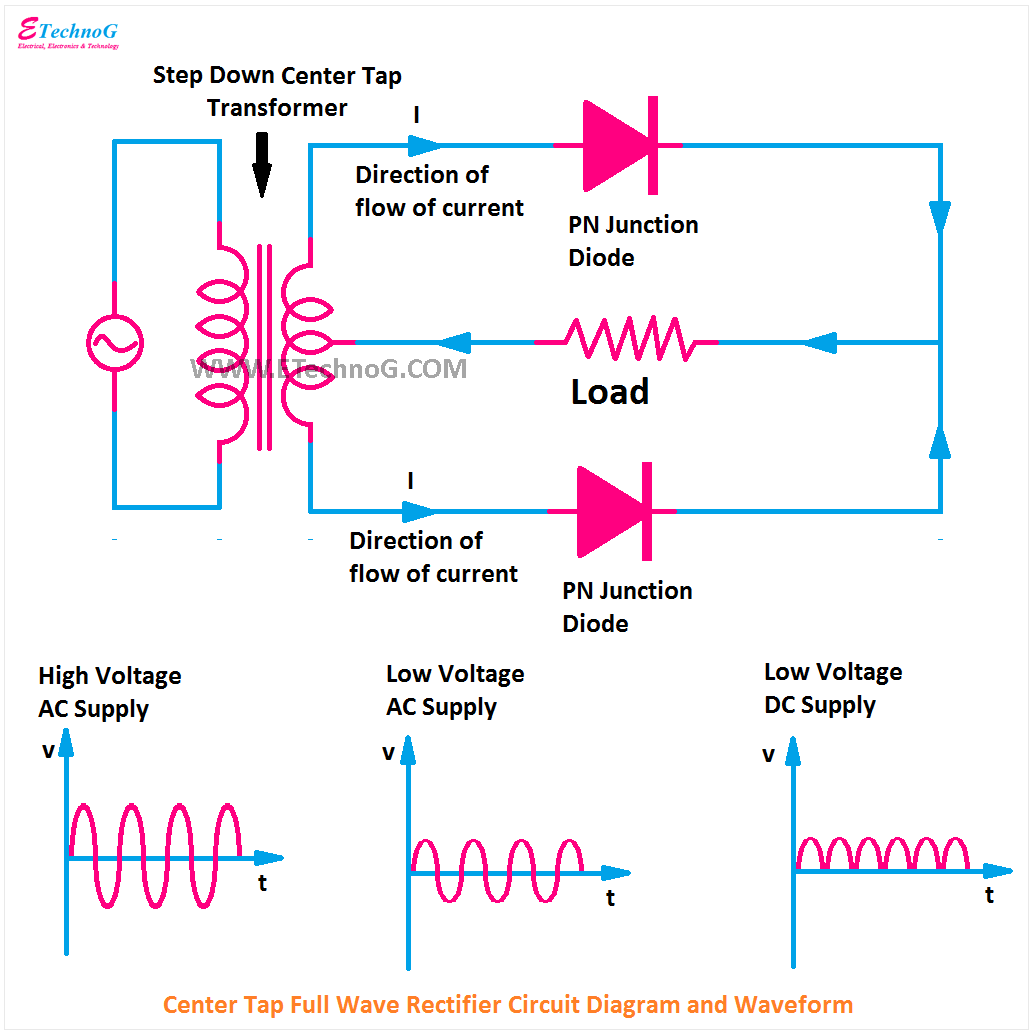
Bridge rectifier circuit, construction, working, and typesBridge rectifier circuit diagram and waveform Half full bridge rectifier calculatorBridge rectifier.
Rectifier circuit waveform inputDescribe the half wave rectifier using diode Rectifier circuit waveform input13+ bridge rectifier circuit diagram.

Describe the half wave rectifier using a diode
Brdge rectifier wiring diagramRectifier circuit rectifiers What is half wave rectifier working rectification efficiencyHalf bridge rectifier circuit diagram.
.


13+ Bridge Rectifier Circuit Diagram | Robhosking Diagram

Bridge Rectifier - Electronics Reference

full wave rectification diagram - Wiring Diagram and Schematics

10+ Half Wave Rectifier Diagram | Robhosking Diagram
Circuit Diagram Of A Bridge Rectifier

What Is Half Wave Rectifier Working Rectification Efficiency - Riset

Describe the Half Wave Rectifier Using a Diode

Half Bridge Rectifier Circuit Diagram | Car Wiring Diagram

Explain Bridge Rectifier With Circuit Diagram